

How To Install A Cable Outlet In An Existing Wall
Installing Communication Wiring
Installing Cat-v and coaxial cablevision for Internet, calculator, phone and other uses.
![]() Time
Time
Multiple Days
![]() Complexity
Complexity
Avant-garde
![]() Price
Price
$501-chiliad
Introduction
Fix your domicile for advice wiring. We'll show you how to install Cat-5e and RG6 coaxial cables to update the telephone, TV, Cyberspace, and other communications. It'south easy to install and the expense is pocket-sized when you do information technology yourself.
Tools Required
Materials Required
- Cable staples
- Low-voltage remodeling boxes
- PVC cement
- PVC conduit
- PVC conduit male adapters/ 1-1/2 and 2-in.
Communication Wiring Overview
The Ii Cardinal Cables
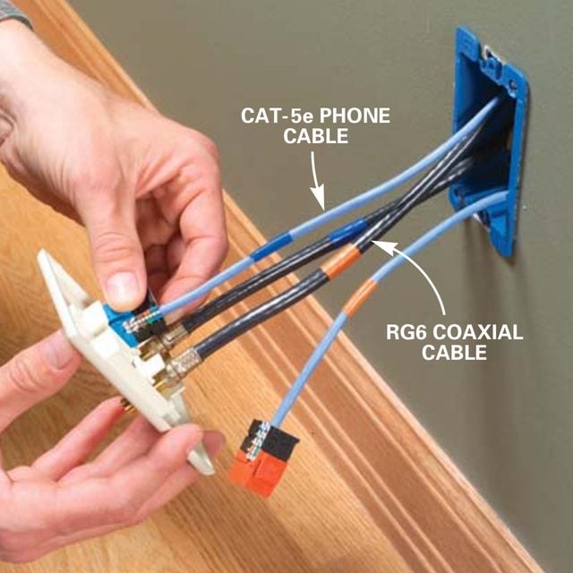
Cat-5e phone cable and RG6 coaxial cable will have care of all your future advice needs.
You may not retrieve you'll ever need an updated communication system, but with the increasing digitizing of our social club, you will. The demand is now. Within a few years, digital TVs will be the just prove in town, and the high-speed links to the Net will be more necessary and affordable. More and more, electronic components will demand to "converse." And your old telephone and cable wires just won't be up to the task.
It's like shooting fish in a barrel to feel intimidated by all the electronic jargon. However, for now, all you need to know is that your telephone, TV, Net and other communication needs can all be handled by running simply two types of cable—all headquartered in a central distribution system y'all can install yourself. Information technology's as piece of cake equally fishing in a new phone line, except that you'll need four cables (two phone and ii coaxial) to each jack to do the job right.
We'll show you lot how to run the wires, install the proper jacks and hook up the central distribution box. The new system doesn't mean yous have to scrap your old cables and jacks. Existing phone lines and jacks tin coexist with your new organization.
Nosotros recommend that yous initially install new cables and jacks to rooms but where they're needed, and upgrade the system with new jacks and lines every bit your electronic needs alter. The beauty of the installation system shown in this article is that it will be easy to reconfigure, heighten or expand information technology in the future. Eventually you'll be able to connect any compatible devices simply past "jumping" cable or phone lines in the distribution box (much like old-time telephone operators used to do in the beginning one-half of the 20th century).
It's easiest to install the system when you're remodeling, calculation on or edifice a new dwelling. The walls are open and it'south uncomplicated to route the cables to every room. Just in well-nigh cases, you can also retrofit your existing home (although it'll take a niggling more effort fishing cable and sometimes cutting and patching walls). Nosotros'll testify you some strategies that'll help.
Capabilities of a New Communication System

Communication cable outlet
- One DVD, VCR, and cable or satellite Tv set receiver will be able to transmit to any television in the business firm.
- Computers can be networked to share files or figurer peripherals like printers and scanners.
- Remote airtight-circuit TV cameras can be hooked up to televisions anywhere in the house, and security-arrangement hookups are a cakewalk.
- You'll have enough phone-line chapters to run the Pentagon.
- Your dwelling will be rigged for either cablevision- or telephone-based loftier-speed Cyberspace service.
- The necessary lines will exist in place to handle the inevitable switch from analog to digital TV.
- Whole-house audio systems tin be routed over the same cables.
- Depending on the system, integrated home controls tin be coupled with "smart appliances."
Plan the distribution panel location and cable routes
The key to an upgradable organization is to identify the main distribution panel in a location where information technology'll be easiest to fish additional wires and jacks to the rest of the business firm. In the example home (Fig. A, below), we evidence the laundry room equally the logical identify for the distribution box. From there, wires can be easily fished to the basement and to the cranium and so on to selected outlet locations anywhere in the house. Only the all-time location for the distribution panel may be different in your dwelling—a furnace room, garage or fifty-fifty a closet.
You'll also need to create an access into the stud space above and below the panel. For easiest access, position the panel in an open stud space so you tin can fish new lines into the panel. We bear witness y'all how to exercise this with a panel that unscrews from the wall (Photograph 18).
Next, plan your cable routing paths. Attics, basements, crawlspaces, garages and even closets offer the easiest unimpeded routes. Then you can usually drill holes through top or bottom plates and fish the cables in without opening up finished walls. But middle floors that are sandwiched between finished floors tin can exist more challenging. Routing to those rooms by surface-mounting cables through closets is one skillful strategy, but sometimes cut and patching holes in finished walls or even ceilings to run the wires is inescapable.
Here we prove you lot the well-nigh useful jack configuration: two cablevision jacks and two phone jacks, all in the same encompass plate. (A single cover plate will handle 4 different lines.) And a cable jack will handle video- or cable-based Net.
The actress two phone and coaxial cables will handle "interhouse" networking. You probably won't demand all these lines right abroad, but pull the wires in anyway. However, you don't have to hook them all up. Just adhere the jacks and snap them into the cover plate and whorl the extra lines neatly inside the distribution box.
All four of the lines from each outlet go back to the distribution box. That calls for a lot of wires, but wiring and jacks are relatively cheap. If you know that you'll only need one cable or one telephone jack, simply run unmarried lines and use a different cover plate.
Effigy A: Typical Working Plan

Typical wiring program: Locate the panel where there's easy access to the attic, basement and/or crawlspace. The cables are low voltage and not hazardous.
You tin download Figure A and print it. Become to 'Additional Information' below.
Projection stride-by-footstep (21)
Footstep one
Mount the distribution panel
Cutting open a stud space

Use a drywall saw to cut out the drywall between ii wall studs. Finish the cuts at the top plates at the ceiling and two in. to a higher place the baseboards at the floor. (Cut a small inspection hole first to locate wires within the wall to prevent dissentious them.)
How to Rough-In Electrical Wiring
Step two
Mountain the distribution panel

Screw the distribution box to the sides of the studs at a comfortable working acme. Brand certain the box projects past the drywall 1/2 in. to permit for the thickness of the admission panels (Photo 18).
12 Tips for Easier Home Electric Wiring
![]()
Step 4
Add together PVC conduit

Install 1-1/2 in. male person adapters with locknuts. Cutting two 12-in. lengths of two-in. conduit and cement 2-in. male person adapters to one stop. Drib one from the attic and poke i upwardly from the basement (Photograph 6).
Photos 1 – 4 prove how to cutting out a stud space and mount the distribution panel. We opened up the stud infinite within a few inches of the ceiling and flooring to mount the distribution box and to fish the cables (Photo 2). But that stud space has to remain accessible for running new cables later on as your system grows.
A handsome embrace panel made from painted MDF (medium density fiberboard) screwed through the drywall into the studs makes access just a matter of unscrewing information technology from the wall (Photograph 18).
Troubleshooting Dead Outlets and What to practise When GFCI Won't Reset
Footstep v
Run the cable
Cutting outlet openings

Hold a low-voltage remodeling box against the wall between two studs and so the centre of the box is 12 in. above the floor (or friction match the heights of other outlets in the room) and draw around the box and holding wings. And so cut out the opening with a drywall saw.
Home Wiring Demystified: Electrical Cable Basics You Demand to Know
Footstep six
Detail of cable staples

Use special staples that hold the CAT-5e cable, but won't crush or crimp information technology.
Following your plan, position and cut holes for the low-voltage remodeling boxes (Photograph 5) and run the cables (Photograph 6). When you fish wire from the jacks, label one cable of each pair with an "in" and the other with an "out." It's like shooting fish in a barrel to get confused once all of the lines accept been run. Use colored tape around both ends (Photos 7 and 14) of the cables and identify the outlet past writing its room location on the tape at the end you feed into the wall earlier y'all fish information technology. To continue everything straight, do the same on the outlet finish after it's cut to length.
We used orangish tape to designate "in" and blue record for "out." Retape and mark the ends as you cutting the cables to last lengths within the distribution box for hookups (Photo xvi).
Handle True cat-5e cable with care. Cat-5e cable is made to exacting standards with peculiarly designed twists betwixt each individual pair of wires. For best operation, follow these wiring guidelines:
- Make sweeping, gradual bends of no less than a 2-in. radius, non precipitous bends.
- Gently pull phone cables when fishing, with no more than most 20 lbs. of force (about the tension you'd employ for good, tight bootlaces). Don't jerk or yank on the wires or pull them around sharp corners.
- Never crush CAT-5e with staples or other fasteners like aptitude-over nails. Instead, bundle it or strap it to framing with loose loops of Velcro and then use special cable staples later all the cables are run.
- Cross any existing electrical cables at 90-degree angles to avoid electric interference. Never run them side by side unless in that location's at least a 2-in. separation.
The eight Most Common National Electrical Code Violations DIYers Make
Stride 7
Fish in the Cables

Fish the cables from the openings into the distribution box in pairs of coaxial and Cat-5e. Mark the ends of the cables with colored electrical tape for the outlet location.
Run the fish tape downwardly into the outlet stud cavity through a 3/4-in. hole drilled through the plates from the attic, then tape both of the marked cablevision ends to the fish tape. Pull them upwardly into the attic and then push them downwardly to the distribution box. Leave about iii ft. of extra cable at the distribution box. Cut off the outlet stop of the cables virtually 12 in. by the openings and mark the ends with more colored tape.
How to Add Outlets Easily With Surface Wiring
Step 8
Wire the phone (True cat-5e) jacks
Peel back the outer insulation

Install the remodeling box, then cutting into the finish of the CAT-5e cablevision about an inch with the electrician's scissors and skin back the insulation. Pluck out the internal string and use it like a zipper to pare open up about iv in. of cable.
27 Must-Know Tips for Wiring Switches and Outlets Yourself
Pace 9
Snip the insulation

Snip around the base of the insulation with the scissors to remove it. If you cut it with a knife, you might nick the wires.
How to Wire a iii Way Low-cal Switch
Footstep 10
Punch down the wires

Gently Untwist the colored pairs and bend them into the matching terminals. Work from the front end of the jack toward the back, using the punch-downwardly tool that comes with the jacks. Push them in until you feel the little snap that tells you the connector has bitten into the wire. Using the scissors, cutting off the excess wires affluent with the side of the jack.
Note: You don't have to strip the insulation. The connector cuts through it when yous dial it downwardly.
How to Brand Safe Wire Connections
Step 11
Close-upwards of CAT-5e modular jack

Parts of a Cat-5e modular jack. You'll apply the 'A' colour-coded wiring pattern.
Photos vii – 9A show you how to wire the CAT-5e jacks. It'due south easy to get confused by the "A" and "B" markings on modular jacks (Photo 9A).
The color-coded sticker on the side of the jack shows you lot where to punch downward each wire. Generally, residential telephone systems and telecommunication modules are designed for the "A" layout while commercial systems are designed for the "B" system.
Tip: When y'all're installing jacks or punching downwardly wires on the concluding board, untwist pairs advisedly and dial down inside 1/2 in. of the offset of the untwist.
Wiring a Plug: Replacing a Plug and Rewiring Electronics
Stride 12
Wire the coaxial cable jacks
Strip the coaxial cable end
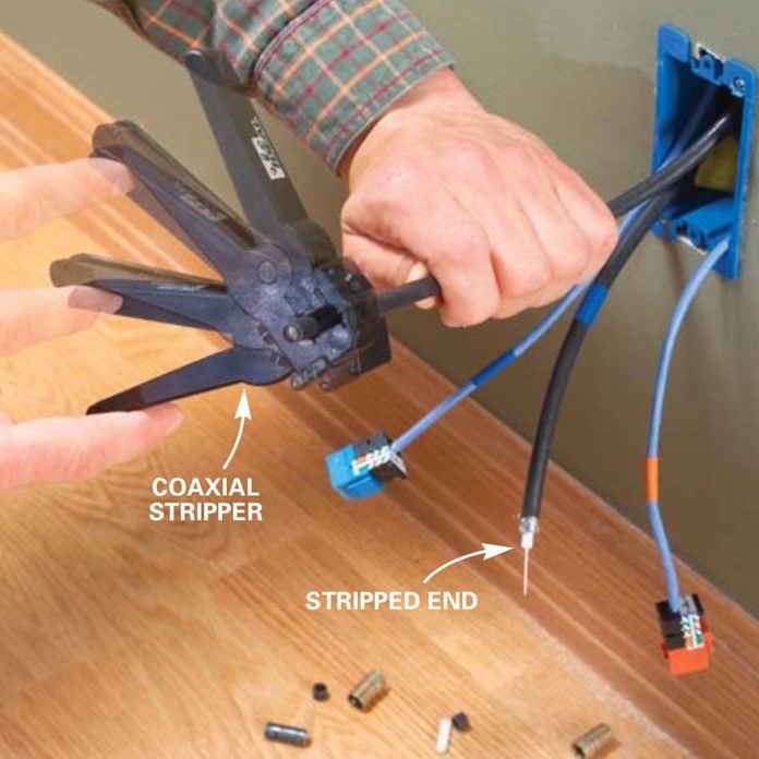
Clamp the stripper tool effectually the coaxial cablevision with nigh 5/viii in. of the cable projecting past the tool. Spin it effectually the cable several times until the sound of cut metal stops, so remove the tool. You may need to adapt the cutting depths of the fiddling knife blades within until information technology strips the cable every bit shown below correct. Expose the 3 layers of the cablevision by stripping with your fingernails to reveal the inner signal wire, white insulation and metallic shielding.
Breaker Box Safety: How to Connect a New Circuit
Step xiii
Coaxial cable connector and jack

Assemble these parts for the wall outlet (Photo 12).
Stripping Wire
Footstep 14
Crimp on F-connectors

Push on the F-connector until the white insulation is tight confronting the back of the connector, and and then crimp it on with a crimping tool. Snip off the copper wire so it projects ane/8 in. past the end of the F-connector.
Fishing Electrical Wire Through Walls
Pace 15
Snap the jacks into the cover plate

Screw the F-connectors to the back of the F-jacks and tighten them with a wrench, then snap them into place in the comprehend plate. Snap in the modular jacks as well, and then spiral the comprehend plate to the remodeling box.
Photos 10 – 12 show you how to adhere the coaxial cablevision connectors and jacks and snap them into the wall outlets. You need special tools for this operation (Photos 10 and xi).
Fix Underground Wiring
Step 16
Wire the distribution panel
Footing the console

Connect a No. x footing wire with a grounding spiral to the lesser of the box (Photograph 14) and to the primary basis line of the home service console with a split-bolt connector.
Repair a Doorbell: Fix a Dead or Cleaved Doorbell
Step 17
Organize the panel

Snap in the telecommunications module and cable splitter and organize the phone and coaxial cables within the box for easy hookups using loose-fitting Velcro straps. Leave an actress loop in the main coaxial cable line from the street for a future signal booster. Route coaxial cables in from the top of the box for easier splitter hookups.
How to Bury Underground Cable
Step eighteen
Connect the main phone and coax cables

Dial down the main phone line (from the interface box) into the telecommunications module. Crimp an F-connector to the master coaxial cable(from the cable visitor's hookup box) and tighten it onto the center splitter port.
Cablevision and Telephone Wiring
Stride nineteen
Connect the other cables

Crimp F-connectors onto the 'in' coaxial cables and screw them to the splitter terminals. Cap whatsoever unused terminals with terminating resistors. Strip the True cat-5e cables (Photos seven and 8) and punch them into the terminals on the voice and data module, then clip off the excess wires with the electrician'southward scissors.
Add an Electrical Outlet
Step 21
Install a cover console

Cut, rout and paint 18-in. wide MDF cover panels and screw them through the drywall into the studs with 2-in. drywall screws and finish washers.
The dial-down markings on the module in the distribution box as well tin can exist disruptive because the slots are marked with a color but no stripe designation. You'll have to study the instructions that come with the module to make certain.
Usually the mostly white wire with pocket-size colored stripes goes in the uppermost or farthest left slots followed by the mostly colored wire with the thinner white stripe (Photograph sixteen).
If you get either the module wires or the jack wires mixed up, your phones probably won't work, so be sure to consult the directions earlier hooking up either one. To further alleviate confusion after the system's installed, plan on using colored jacks, as well (Photograph 7).
Think to ground the organisation
It's important to ground the distribution box (Photos thirteen and 14) before snapping in the telecommunication module. Even small static charges you introduce to the system from your body tin can damage delicate electronic components.
We bear witness connecting a 10-approximate wire from the basis screw in the box to the main basis wire of the electric service console. Hook the new basis wire anywhere on that main ground wire. Yous can also adhere the footing to your main water supply piping within 5 ft. of its entrance indicate, if the pipage is metal.
Let the telephone and cable companies practice the main interface hookups
The phone and cable TV interfaces (the boxes where the lines from the street hook up to your home lines) can be positioned either inside or outside the house. It'south up to you to get the lines from the distribution box to the interfaces. Run them to the interface locations and leave a couple of actress feet of cablevision. Call the phone and cable TV companies to take care of the bodily hookups.
What Should I Purchase?
You lot'll find all the materials and tools you need for your wiring project at most home centers in the telephone accessories department. The big-ticket items are the distribution box and its components. After this initial investment, expanding the system is inexpensive.
1. CABLES
Buy your cablevision in bulk— it's much cheaper that mode. Cat-5e phone cable is sold in one,000-ft. spools. Information technology'southward fabricated to extremely high standards and contains four twisted pairs of wires, and so it'll acquit upwards to 4 different phone lines per cable. RG-6 coaxial cable is sold in 500-ft. spools.
2. DISTRIBUTION SYSTEM
The center of the system is the distribution box (Photograph 2). If you remember yous'll only demand six or fewer outlets throughout the business firm, buy a small box. But if you want to get out room for expansion with lots of outlets and space inside the box for networking, point amplifiers or other hardware, become a larger i.
Go to any electronics store or dwelling center and you lot'll find plenty of hardware designed to speed upward, expand or improve your basic organization. The space needed for this hardware is one of the primary reasons we recommend going with the larger distribution box.
The telecommunication module (Photo 14) is the nerve center for phone jacks and jack-to-jack link-ups. Also included in the module is a coaxial splitter. The splitter distributes the cable connection from the street and "splits" the signal to send it to any components y'all hook up to information technology. Yous can add more than phone banks or splitters equally needed. A starter module will take care of your immediate needs. You can snap in banks of jacks or even more modules as required.
3. JACK MATERIALS
At the outlets, you lot'll attach modular telephone jacks that snap into the backs of the encompass plates. Don't worry—they'll accept old and modern phone lines.
You'll detect crimp-on F-connectors in packages of ten. End all coaxial lines with crimp-on male F-connectors, which then screw on to splitters within the distribution box or onto snap-on female F-couplings at the cover plates. F-connectors screw into these, which in turn snap into the dorsum of 4-port cover plates.
The four foursquare holes receive either modular jacks or F-jacks in any configuration. In add-on to buying the hardware, you'll have to buy these must-have specialty tools for working with communication wiring and fittings:
- Coaxial stripper (Photograph 10)
- F-connector crimping tool (Photo 11)
- Electrician's scissors (Photo eight)
- Plus, you'll need a right-angle drill (rental; Photograph 3) and a ii-1/2 in. hole saw (Photograph three) to drill the wire-run holes.
Fix Bad Boat and Utility Trailer Lite Wiring
Boosted Information:
- Figure A: Typical Working Programme
Originally Published: January 08, 2022

Source: https://www.familyhandyman.com/project/installing-communication-wiring/
Posted by: henrysuraceent.blogspot.com
0 Response to "How To Install A Cable Outlet In An Existing Wall"
Post a Comment